Symboloogy Basic Electrical and Electronic
| Symbol | Description | Symbol | Description | |
|---|---|---|---|---|
Symbols passive components | ||||
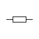 | Resistor IEC system + symbols | 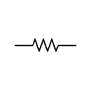 | Resistor NEMA system + symbols | |
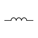 | Inductor / Coil + symbols | 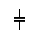 | Capacitor + symbols | |
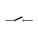 | Switch + symbols | 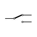 | Circuit switch + symbols | |
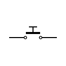 | Pushbutton + symbols | 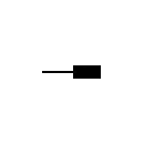 | Plug IEC system + symbols | |
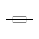 | Fuse + symbols | 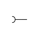 | Female plug IEC system + symbols | |
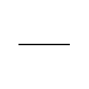 | Electric line + symbols | 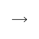 | Plug NEMA system + symbols | |
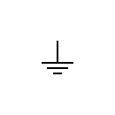 | Ground + symbols | 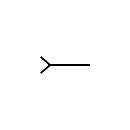 | Female plug NEMA system + symbols | |
Symbols active components | ||||
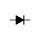 | Diode + symbols | 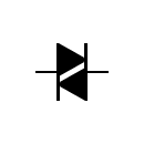 | Diac + symbols | |
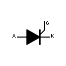 | Thyristor + symbols | 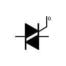 | Triac + symbols | |
 | IC / Chip + symbols | 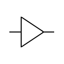 | Amplifier + symbols | |
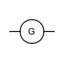 | Electric generator + symbols | 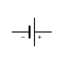 | Battery + symbols | |
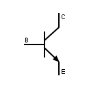 | Transistor + symbols |  | Vacuum tube / Electron tube e.g. Diode + symbols | |
Symbols of Logic Gates (Digital electronic) | ||||
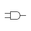 | AND gate ANSI system + symbols | 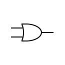 | OR gate ANSI system + symbols | |
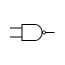 | NAND gate ANSI system + symbols | 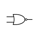 | NOR gate ANSI system + symbols | |
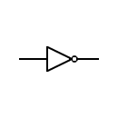 | Logic inverter + symbols | 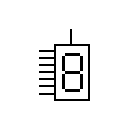 | Display 7-segment LED + symbols | |
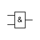 | AND gate British system + symbols | 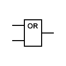 | OR gate British system + symbols | |
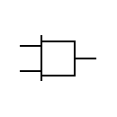 | AND gate NEMA system + symbols | 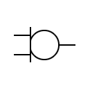 | OR gate NEMA system + symbols | |
Electrical test & control equipment symbols | ||||
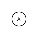 | Ammeter + symbols | 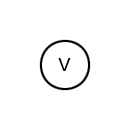 | Voltmeter + symbols | |
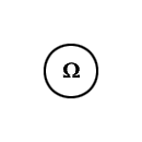 | Ohmmeter + symbols | 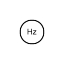 | Frequency meter + symbols | |
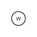 | Wattmeter + symbols | 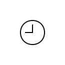 | Electric clock + symbols | |
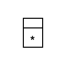 | Electrical counter / Integrator The asterisk is replaced by the letter or symbol for the quantity count + symbols | 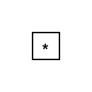 | Recording instrument The asterisk is replaced by the letter or symbol of the magnitude recorded + symbols | |
Other basic electrical and electronic symbols | ||||
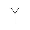 | Antenna / Aerial + symbols |  | Speaker + symbols | |
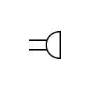 | Microphone + symbols | 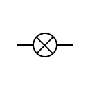 | Lamp / Light Bulb + symbols | |
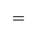 | Direct current, DC + symbols | 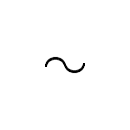 | Alternating current, AC + symbols | |
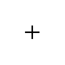 | Positive polarity + symbols | 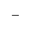 | Negative polarity + symbols | |
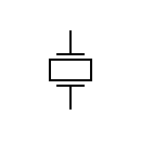 | Piezoelectric crystal + symbols | 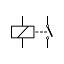 | Relay (Coil and Switch) + symbols | |
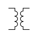 | Electric transformer + symbols | 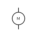 | Electric motor + symbols | |
Index of all Electrical and Electronic Symbols | ||||
Wires Represents a conductor that conducts electrical current. Also called a power line or electric line or wire. | Connected Wires Represents the connection of two conductors. Dot shows the junction point. | Unconnected Wires Represents two unconnected wires/conductors. |
Input Bus Line Represents a bus for input or incoming data. | Output Bus Line Represents a bus for output or outgoing data. | Terminal Represents start or end point. |
Bus Line Represents a number of conductors joined together to form a bus wire. | ||
Push Button (Normally Open) This switch is in ON state when the button is pressed otherwise it is in OFF state. | Push Button (Normally Closed) This switch is initially in ON state. This goes to OFF state when it is released. | Spst Switch Single pole single throw is abbreviated as SPST. This acts as ON/OFF switch. Poles define the number of circuits it can be connected to and throws defines the number of positions that a pole connects. |
Spdt Switch Single pole double throw is abbreviated as SPDT. This switch allows the current to flow in any one of the two directions by adjusting its position. | Dpst Switch Double pole single throw is abbreviated as DPST. This switch can drive two circuits at a time. | Dpdt Switch Double pole double throw is the full form of DPDT. This can connect the four circuits by changing the position. |
Relay Switch This represents the relay switch. This can control the AC Loads using the DC voltage applied to the coil. | ||
AC Supply This represents AC supply in the circuit. | DC Supply This represents the DC power supply. It applies DC supply to the circuit. | Constant Current Source The symbol represents an independent current source which delivers constant current. |
Controlled current Source It is a dependent current source. Usually depends on other sources (voltage or current). | Controlled Voltage Source It is a dependent voltage source. Usually depends on other sources (voltage or current). | Single Cell Battery This provides supply to the circuit. |
Multi Cell Battery Combination of multiple single cell batteries or a single large cell battery. The voltage is usually higher. | ||
| Wave Generators | ||
Sinusoidal Generator Represents sine wave generator. | Pulse Generator Represents pulse or square wave generator. | Triangular Wave Represents triangular wave generator. |
| GROUND SYMBOLS | ||
Ground It is equivalent to theoretical 0V and is used as zero potential reference. It is the potential of perfectly conducting earth. | Signal Ground It is a reference point from which the signal is measured. There may be several signal grounds in a circuit due to the voltage drops in a circuit. | Chassis Ground It acts as a barrier between user and the circuit and prevents electric shock. |
| RESISTOR SYMBOLS | ||
Fixed Resistor It is a device that opposes the flow of current in a circuit. These two symbols are used to represent fixed resistor. | ||
| VARIABLE RESISTOR | ||
Rheostat It is a two terminal variable resistor. They are generally used to control the current in the circuit. Generally used in tuning circuits and power control applications like heaters, ovens etc | Preset It is a mini variable resistor. It is also called Trimmer Resistor or Trim Pot. The resistance is adjusted with rotary control present on top of it with the help of a screw driver. They are used to adjust the sensitivity of the circuit like temperature or light. | Thermistor It is a temperature sensitive resistor. They are used in temperature sensing, current limiting circuits, over-current protection circuits etc. |
Varistor It is a Voltage Dependent Resistor. It has non-linear current-voltage characteristics. Generally used in circuit protection from voltage surges and excessive transient voltages. | Magneto Resistor They are also called as Magnetic Dependent Resistors (MDR). The resistance of magneto resistor varies according to the external magnetic field strength. They are used in electronic compass, ferrous material detection, position sensors etc. | LDR They are also called as Photo Resistors. The resistance of LDR varies with the intensity of the light incident on it. They are generally used in light sensing applications. |
Tapped resistor A wire-wound type fixed resistor with one or more terminals along its length. Generally used in voltage divider applications. | Attenuator It is a device used to lower the power of a signal. They are made from simple voltage dividers and hence can be classified in the family of the resistors. | Memristor The resistance of memristor is varied according to the direction of flow of charge. Memristors can be used in signal processing, logic/computation, non-volatile memory etc. |
| CAPACITOR SYMBOLS | ||
Non Polarized Capacitor Capacitor stores the charge in the form of electrical energy. These two symbols are used for non-polarized capacitor. Non-polarized capacitors are big in size with small capacitance. They can be used in both AC and DC circuits. | Polarized Capacitor Polarized capacitors are small in size but have high capacitance. They are used in DC circuits. They can be used as filters, for bypassing or passing low frequency signals. | Electrolytic Capacitor Almost all electrolytic capacitors are polarized and hence used in DC circuits |
Feed through Capacitor They provide low impedance path to ground for high frequency signals | Variable Capacitor The capacitance of the variable capacitor can be adjusted by turning the knob. They are widely used to adjust the frequency , that is for tuning. | |
| INDUCTORS | ||
Iron Core Inductor These are used as substitutes to ferrite core inductors. Ferrite core or Ferromagnetic inductors have high permeability and require air gap to reduce it. Iron powdered core inductors have this air gap integrated. | Ferrite Core Inductors Core material, in this type of inductors is made of ferrite material. These are mostly used to suppress the interference of electromagnetic waves. | Center Tapped Inductors These are used in coupling of signals, |
Variable Inductors Movable ferrite magnetic core variable inductors are most common. The inductance is varied by sliding the core in or out of the coil. | ||
| DIODES | ||
Pn Junction Diode A PN junction diode allows the current to flow only in forward bias condition. These diodes can be used in clipping and clamping circuits , as rectifiers in dc circuits etc. | Zener Diode In forward bias condition, it acts as normal diode and allows current. It also allows current to flow in reverse bias condition when the voltage reaches a certain break-down point. Generally used in voltage regulator and over voltage protection circuits. | Photodiode Photodiode detects the light energy and converts it into current or voltage by a mechanism called photoelectric effect. These are used in CD players , Cameras etc. |
Led Light emitting diode is similar to PN junction diode but they emit energy in the form of light instead of heat. These are mostly used in indication , lightening applications. | Varactor Diode Varactor diode is called varicap or variable capacitance diode. The capacitance of this diode varies according to the applied input voltage. This is used in frequency controlled oscillators , frequency multipliers etc. | Shockley Diode This is a four layer diode. This had fast switching operation and hence is used in switching applications. |
Schottky Diode It represents Schottky diode. It has low forward voltage drop and it can switch rapidly. Used in voltage clamping, rectifiers. | Tunnel Diode This is also known as Esaki diode.It can switch very fastly and can perform well in micro wave frequency range. This is used in oscillator circuits and micro wave circuits. | Thyristor It consists of four layers of alternating P and N materials. They act as bistable switches and are used in circuits where high voltages and currents are involved. |
Constant Current Diode Also called as Current Limiting Diode or Current Regulating Diode. It limits the current to a specified maximum value. | Laser Diode The laser diode is similar to light emitting diode. The active region is formed in intrinsic region in PIN structure. Laser diodes find its applications in laser printing, laser scanning etc. | |
| TRANSISTOR SYMBOLS | ||
NPN It is made of combination of P-type semiconductor between two N-type semiconductors. It is switched ON when the base-emitter junction is forward biased. They are commonly used for amplifying and switching applications. | PNP It is made of combination of N-type semiconductor between two P-type semiconductors. It is switched ON when the base-emitter junction is reverse biased. These are used for amplifying and switching applications. | |
| JFET | ||
N- Channel JFET N-channel JFET is made by n-type silicon bars which form two PN junctions at the side. Majority charge carriers here are electrons. | P-Channel JFET P-Channel JFET is made by p-type silicon bar which forms two PN junctions at the side. Majority charge carriers here are holes. | |
| MOSFET | ||
Enhancement MOSFET The enhancement mode MOSFET has positive gate operation. It induces negative charges into the n-channel and thus number of negative charges increases, enhancing the channel conductivity. | Depletion MOSFET The depletion mode has negative gate operation. This decreases the width of the depletion layer. |


No comments:
Post a Comment
If you have any doubts please comment